
OpenWRT Setup with DSA VLANs
So, you have an OPNsense firewall.
You have some VLANS set up on that firewall.
You want to send that segregated traffic to your access point - and, have your wireless network as isolated as your lan.
That’s the plan.
OpenWRT 24
There is no longer a switch section of the Network in the OpenWRT LuCI interface. This has been replaced by DSA.
If you try and go to the default bridge, br-lan and move over to the tab, Bridge VLAN filtering and try and Enable VLAN filtering you will break your config and have to roll back.
THIS WILL NOT WORK
Instead, the correct way is to:
Step 1: Make VLANS on OPNsense
We’re going to assume the network configuration of, a router on a stick.
The last device on that stick, the router, is the first configuration we’re goin to make.
You need to setup your VLANS for the switch/accesspoint to use.
A good example is:
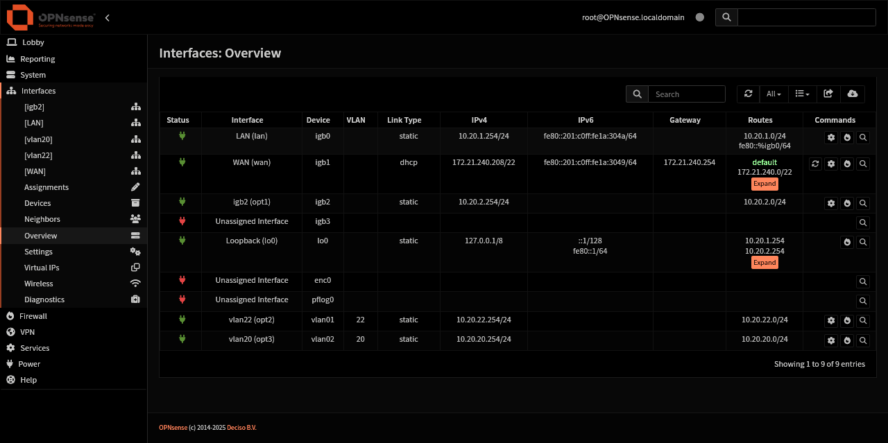 You can see the interfaces, their VLAN assignment and their IP address.
and then:
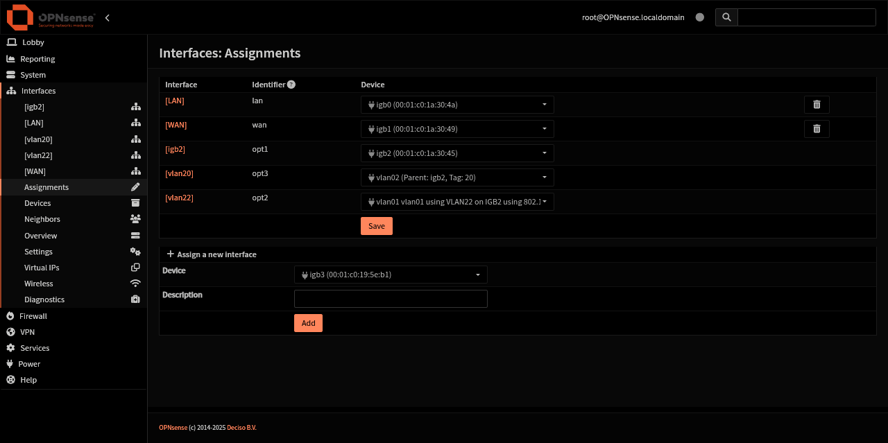 This screenshot demonstrates the interface assignment page.
I also have some screenshots of each VLAN and it’s DHCP settings. So you can see later when we connect to the VLAN, we know we’re connected - we got an IP Address.
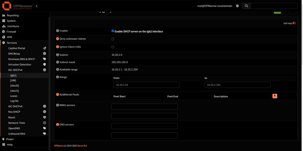 OPNsense DHCP pool range for igb2
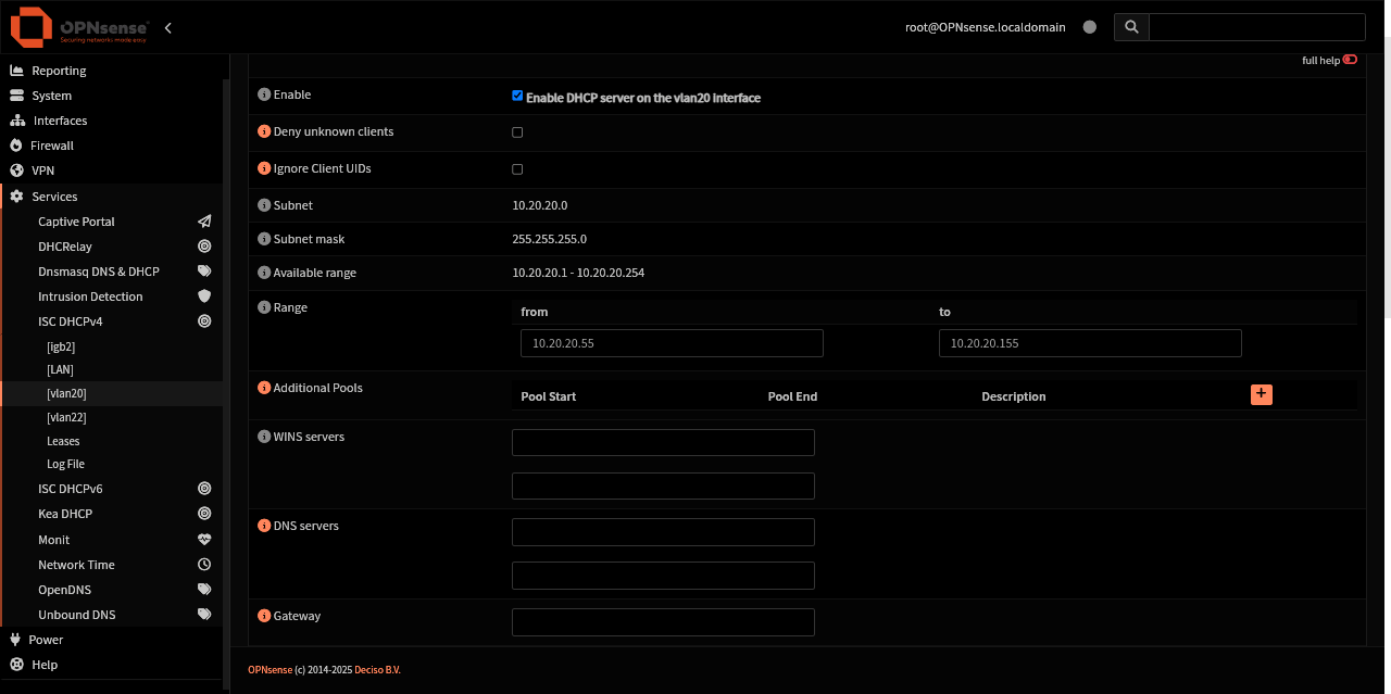 Parent interface, igb2, on VLAN 20’s DHCP pool range
Step 2: Verify physical connections
First, we need to test the connection between OpenWRT and OPNSense and verify there is a working connection between OPNSense and OpenWRT.
The way VLANs work now with DSA is to create them on a bridge, LuCI will make the vlan device, and then you put that vlan device on an Interface.
Sound easy?
The knee bone… is attached to the Upstream VLAN Ethernet Cable … the Upstream Ethernet Cable is Attached to OPNSense …
… Our upstream VLAN Ethernet Cable from OPNSense is also attached to an interface on OpenWRT, in this example lan4.
We are connected with a cable into Port 1, lan1, and are on the LAN bridge, br-lan, so our network connection to OpenWRT will remain.
Step 3: Adding a bridge on OpenWRT
This is all new to OpenWRT 24.
Go to the
Networking > InterfacestabOnce there, we need to make a new bridge, to do this
Click on the
DevicestabClick on the
Add Device Configurationbutton at the bottomA new window will appear.
Change
Device TypetoBridge DeviceDevice Name: anything you like
Bridge ports: select the interface you’re plugging into your opnsense router or a switch with tagged vlans
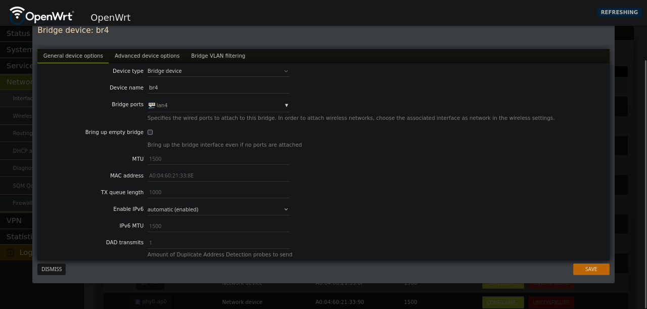 Device Type and Bridge Port for the ethernet port you are plugging into OPNsense
Step 3a: The new way to add a VLAN
This has replaced the Switch section:
Head over to the
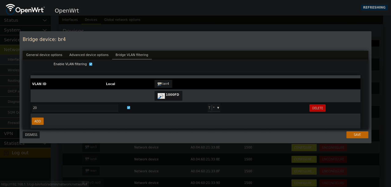
Bridge VLAN filteringtabThis tab will have the option to add VLAN IDs to any selected
lan#on the bridgeHere we’re going to setup our VLAN but sent out untagged traffic
Set the VLAN ID you used in OPNsense
In the drop down, check “Untagged” and “is Primary VLAN”
Please keep the
localcheck box tickedSave
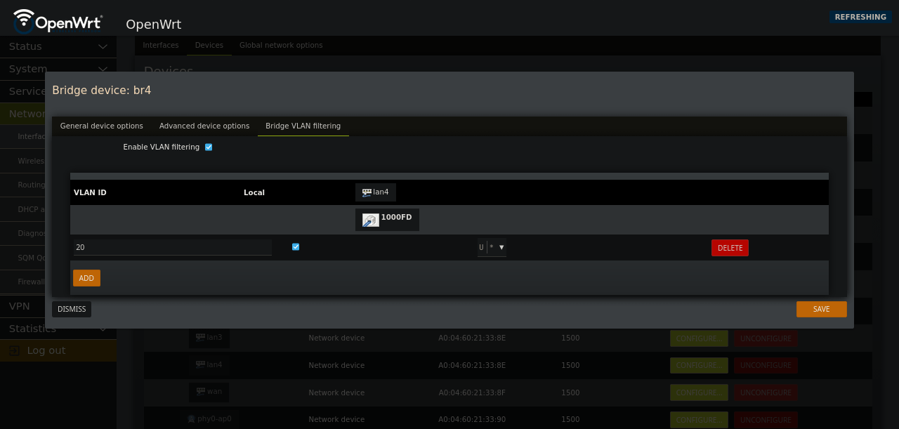 Setting the VLAN ID on lan# to
 U for untagged egress traffic and is Primary VLAN for the Port VID (PVID) ingress traffic. This will ensure our network traffic comes out untagged.
Step 4: Back on the Devices Tab
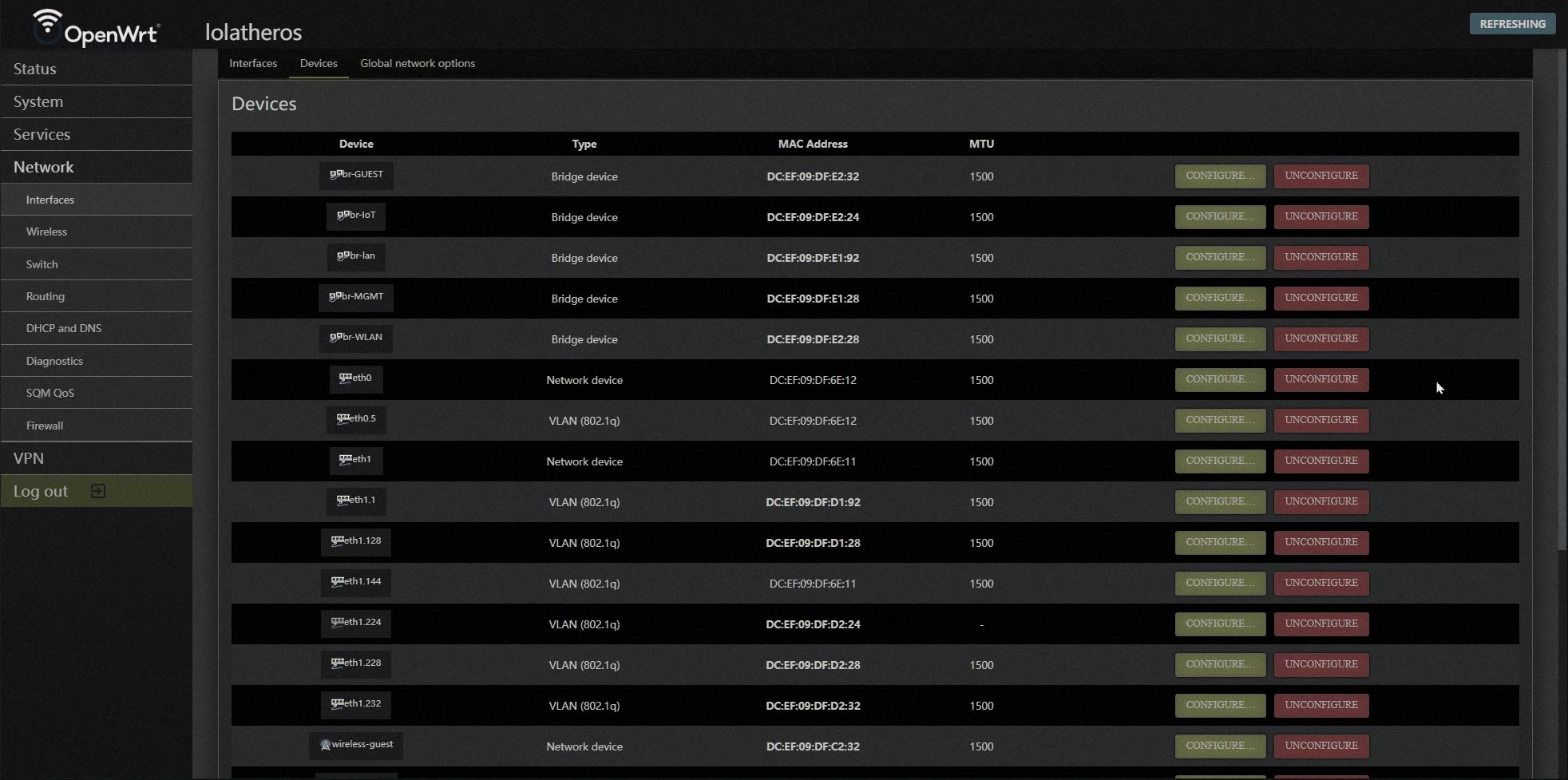
Now you should see the newly created bridge, and your VLAN device.
Local will automattically create the VLAN device in the Devices section
This interface will appear grayed out, as you cannot edit it. It is tied to the
localcheck box and managed in that way.
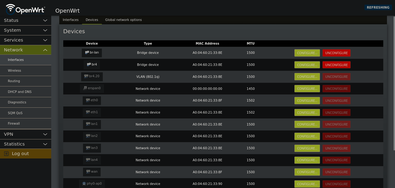 Most everything will be greyed out.
Please note: You can never touch eth1 or eth0 - these are hard wired into the switch.
Take a look at the MAC Addresses, you will see which cpu interface is tied to which network device.
Step 4a: (optional) Explaining how - lan, ports, ethernet - are used.
The R7800 switch chip has 7 ports. Five of those are the Ethernet ports on the outside of the case, and two are internal connections between the switch chip and the CPU chip.
At the CPU end they are accessed as eth0 and eth1. This has nothing to do with the number of processor cores. By default, “eth0” is used for traffic to/from the ISP and “eth1” is for traffic to/from the local network.
Again, dont touch eth0 or eth1 - the setup with these are for the older version of OpenWRT when you had to create a dedicated bridge for each vlan.
Step 4b: Memory lane photos
You can see the old version of OpenWRT and how it handled VLANs and switching:
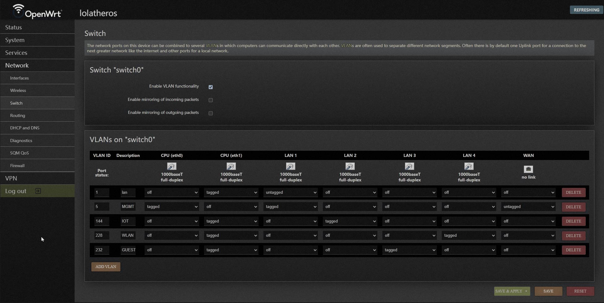 You can see the Switch section of the previous verions of OpenWRT.
 And here is where the devices were generated for your vlan tagging.
Step 5: Adding an interface on OpenWRT
Interfaces allow us to use IP configuration. Without an Interface, we wont be able to directly communicate on the bridge.
Head back over to the
InterfacestabClick on
Add New InterfaceYou can name your interface anything you like (best to name it by use, e.g. - IoT, Guest)
Then under
ProtocolselectDHCP clientUnder Device, select the name of the bridge we made earlier, AND, the
.followed by the VLAN ID you set.Save
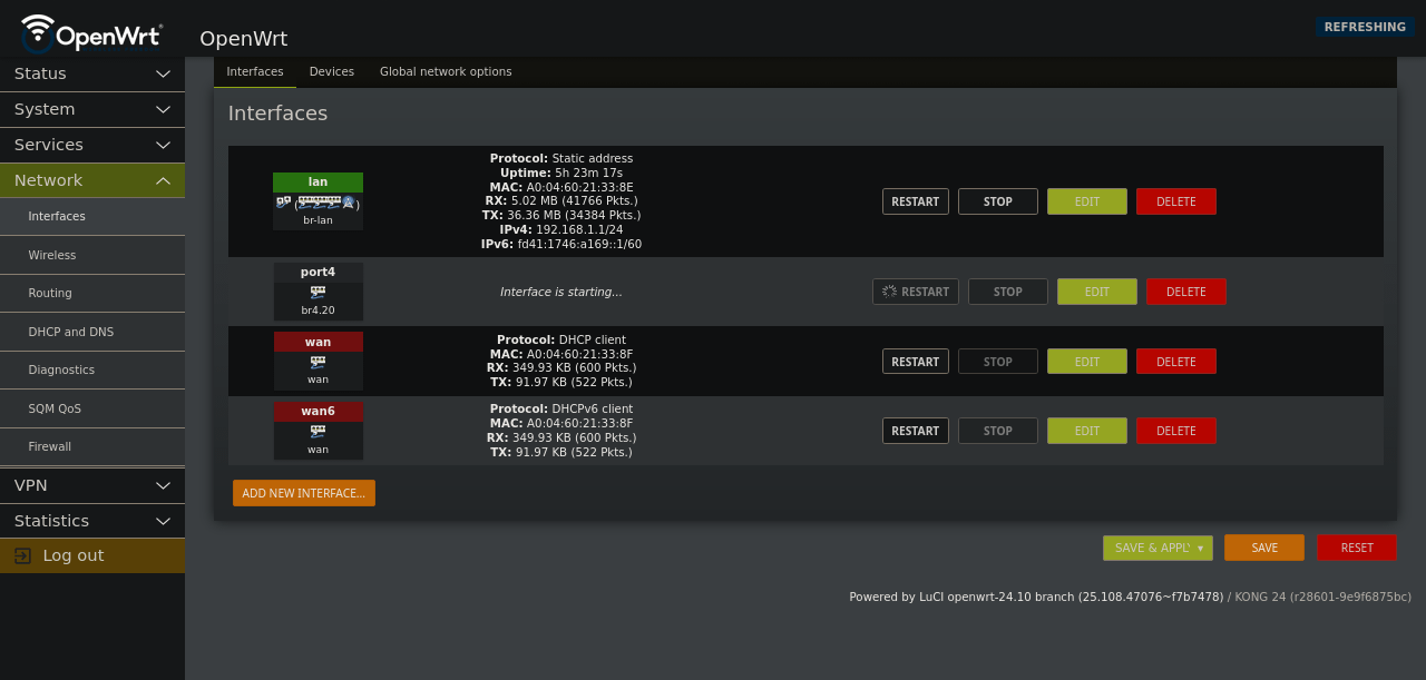
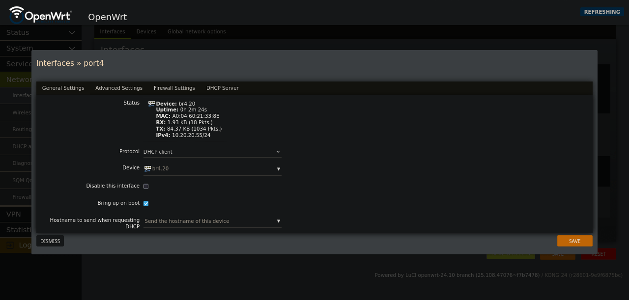 It should look something like
 br4.20
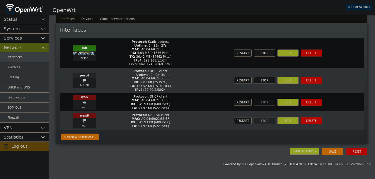 You should now see your new interface and it should have an IP on the untagged subnet for your vlan’s parent interface on OPNsense
Step 6: Make a VLAN bridge device on OpenWRT
The best way to get this working is to:
Modify your bridge
Use the
Bridge VLAN filteringtabFind your VLAN IDs and modify the interface with
TaggedSave
 Modifing the bridge should look something like this.
Step 7: Verify a VLAN connection
You can now go back to interfaces tab.
Hit the restart button on the interface you made earlier
 You can request a new IP by resetting the interface.
 You should have a new IP Address, one on the VLAN network you made.
Step 8: Stay up to date
https://openwrt.org/docs/guide-user/installation/attended.sysupgrade
https://openwrt.org/docs/guide-user/installation/sysupgrade.owut
Screenshot Credit
OpenWRT screen shots are:
KONG 24.10 date 2025-05-13
OpenWRT: Understanding Bonded Bridges and VLAN Limitations
If you’re setting up a bridge in OpenWRT, there’s a key idea to keep in mind: You can only have one bridge per interface. For example, LAN1 can ONLY belong to just one bridge with a single native VLAN.
That means you can’t use that same interface on a different bridge—LAN1 needs to stay tied to the one bridge it’s assigned to, and attempts to use it elsewhere will result in a DEVICE_CLAIM_FAILED error.
So how do you handle multiple VLAN SSIDs on the same interface?
You generate multiple VLANs from that single bridge as needed.
But wait… Are you making the bridge with a bond? Uh, oh!
OpenWRT Bonded Bridges and LACP hashing
This is the crucial part. You can only carry VLANs over a bonded bridge if you use the correct hashing method for traffic distribution, namely encap2+3 for CISCO switches. Here’s what I mean:
layer2+3hashing uses the source and destination MAC addresses (Layer 2) and IP addresses (Layer 3) to determine how outbound traffic spreads across aggregated links. This works well with plain Ethernet and IP packets.encap2+3works likelayer2+3but also examines inner headers in encapsulation or tunneling protocols such as VLAN, VXLAN, GRE, or VPN tunnels. It uses a Linux kernel function (skb_flow_dissect) to identify these inner fields, ensuring traffic inside tunnels is more evenly balanced across links.
You might wonder about the difference in naming conventions: Cisco often uses “encap” to refer to encapsulation headers at Layer 2 and Layer 3, whereas OpenWRT/Linux uses “layer2+3” for added clarity.
For context, I’m using a Cisco SLM2024 switch, which supports these features and is a solid 2007 option for handling VLANs with OpenWRT setups. I’m sure modern switches have better options, but for those that don’t… hope that helped.